The FT7 Series Pipe Mount wind sensor is designed for installation on top of a pipe or post. The sensor-connecting cable is run inside the pipe giving added lightning and environmental protection. The Pipe Mount system is made from materials designed to last for up to 25 years in a marine or offshore environment.
The sensor has additional heating capacity designed to heat the metal adaptor and pipe. This prevents ice from building up on the adaptor and blocking the air flow through the sensor during heavy icing events. The whole pipe mount system is designed to ensure sufficient heat transfer from the sensor into all the metalwork to keep it ice free.
The diagram below shows the installation on top of a wind turbine nacelle. Alignment of the pipe mount adaptor allows the sensor to be repeatedly fitted and automatically aligned with the central axis of the turbine without error.
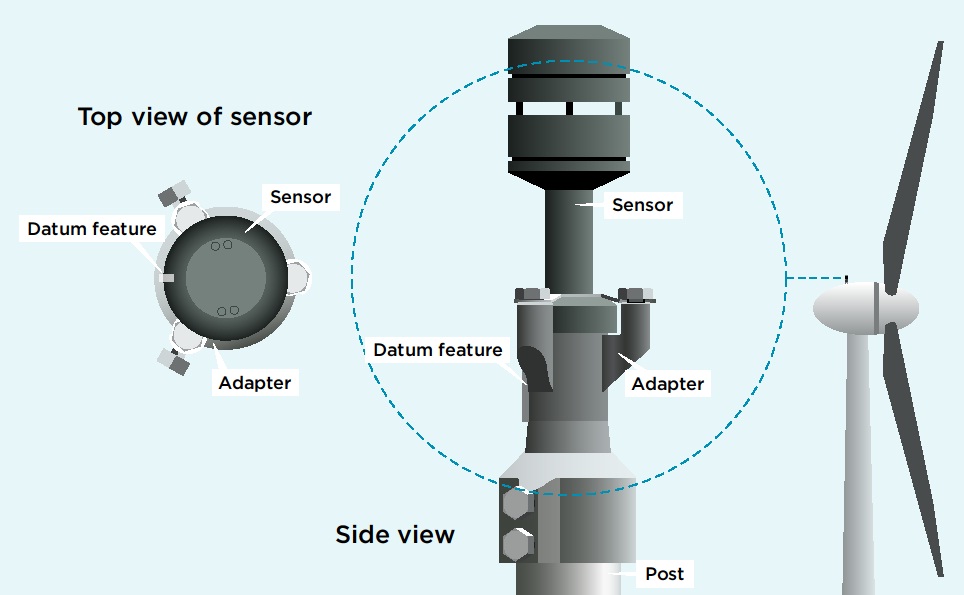
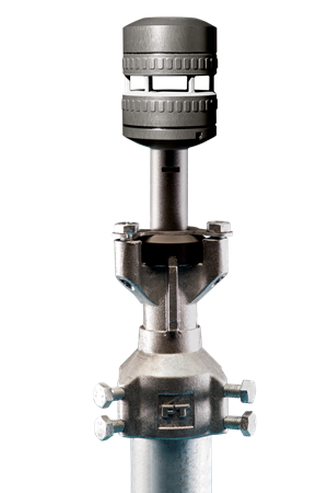
The Pipe Mount sensor is fitted to the pipe or post with the FT designed Pipe Mount Adaptor (FT090). This helps to ensure a robust setup that completely protects the cable from the external environment.
The Pipe Mount Adaptor is designed to be fitted and aligned in the factory or on the ground. This allows the sensor to be removed/replaced without the need to re-align later.
Correct alignment of the sensor is important for yaw control of the turbine. Failure to align the sensor will result in misalignment of the turbine which will affect the power curve.
Use the sensor’s datum marking for alignment with the turbine’s centreline. Datum direction can also be offset in software by using the CF command. See the user manual for more details.
The FT sensor is designed to survive indirect lightning strikes but, like any electrical equipment, it will not survive a direct strike. It is therefore essential that an appropriate lightning interceptor is installed with the sensor. The body of the sensor must be grounded along with the interceptor and grounding must be continuous through to the ground of the turbine or met mast on which the sensor is mounted. This is to ensure that the majority of the lightning current gets diverted away from the sensor.
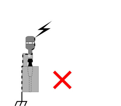
Direct lightning strike |
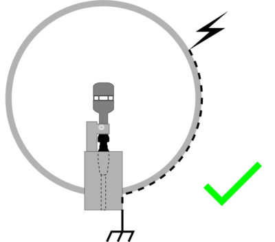
Indirect lightning strike |
The material of the mounting and lightning interceptor should ideally be made from high-grade aluminium, or if icing is unlikely to be an issue, the galvanised steel can be used as an alternative. Both of these materials have good conductive and anti-corrosion properties.
The sensor’s cable should have its shielding terminated at both ends – 360° terminated at the computer/ datalogger end in the cabinet wall using in an EMC cable gland. Signal wires should then pass through surge protection devices which must be correctly rated as per the Installation Section of the User Manual.
All mating surfaces must be free of non-conductive coatings and corrosion in order to ensure minimum resistance to ground.
FT Technologies can provide a lightning installation checklist which is designed to help you with checking that your sensor and computer/datalogger are adequately protected against lightning strikes. Contact us to request this checklist.
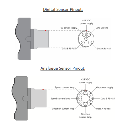
The FT7 Series sensor requires a supply voltage of 12V-30V DC (24V DC). The power supply should be capable of supplying of 6A (max) if the heater is enabled, or 30mA if it is not. All electrical connections are made to the sensor via a multipole connectors manufactured by Fischer or ODU (in the case of digital sensors, using cable side connectors of the following part numbers: SE104Z053-130/8.7 or SX2F1C-P05NJH9-0001 respectively. In the case of analogue sensors, using cable side connectors: SS104Z129-1 or SX2F1C-P08NJH9-0001 respectively).
The pinout from the base of the Direct Mount sensor is as follows:
Heater and Set Point Temperature
To get the best from your sensor in icing conditions, the heater should be enabled and set to 30°C. This will help to prevent icing and water condensing in the measurement cavity, thus maximising data availability. In addition, a constant body temperature is better for the longevity of the electronic components.
The heater set point value can be adjusted using the HT command (refer to the user manual for more details) or alternatively using our Acu-Test Packs.
If the default current limit of 4A proves insufficient then it can be raised in software to 6A (in model V22 and above) but you must ensure that your power supply and cable can support at least 6 Amps.
Filtering
Always keep the sensor’s internal filter enabled. Where the wind sensor is used for control purposes, always use filtered data. The sensor is dispatched with the internal filter enabled by default and set to a filter length of 1.6 seconds.
Status Flag (Error Flag)
Analogue: The sensor indicates errors and out-of-range measurements by setting the current loops to levels outside of the normal 4-20mA range. It is important that your data logging equipment or control system can process this invalid data appropriately. See the manual for more details.
Digital: The sensor has an internal self-checking mechanism. It signals that a reading is invalid by setting an error flag character with in the wind velocity output message:
$WI,WVP=020.0,045,1*52〈cr〉〈lf〉
A value other than “0” here indicates an invalid reading of some sort was detected.
It is important that your data logging equipment or control system can process this invalid data appropriately. See the manual for more details on this.
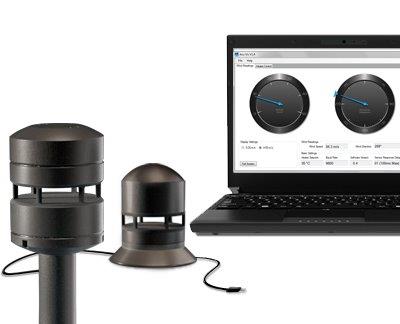 Testing of sensors is best performed with our Acu-Test Pack, which allows you to connect the sensor to a PC via a USB cable and view wind speed and direction readings in real-time. The pack also allows you to change some settings such as heater set point temperature.
In the case of digital sensors, a serial emulator program (such as Tera Term or HyperTerminal) will also function with the cable supplied in the Acu-Test Pack and is another way of testing communication. This allows the user to send commands and receive data from the sensor. Please note, however, that FT Technologies is not responsible for the content of external sites.
Further details are available in the product manual. Request a manual.
For details on cables and connectors please refer to Accessories.
