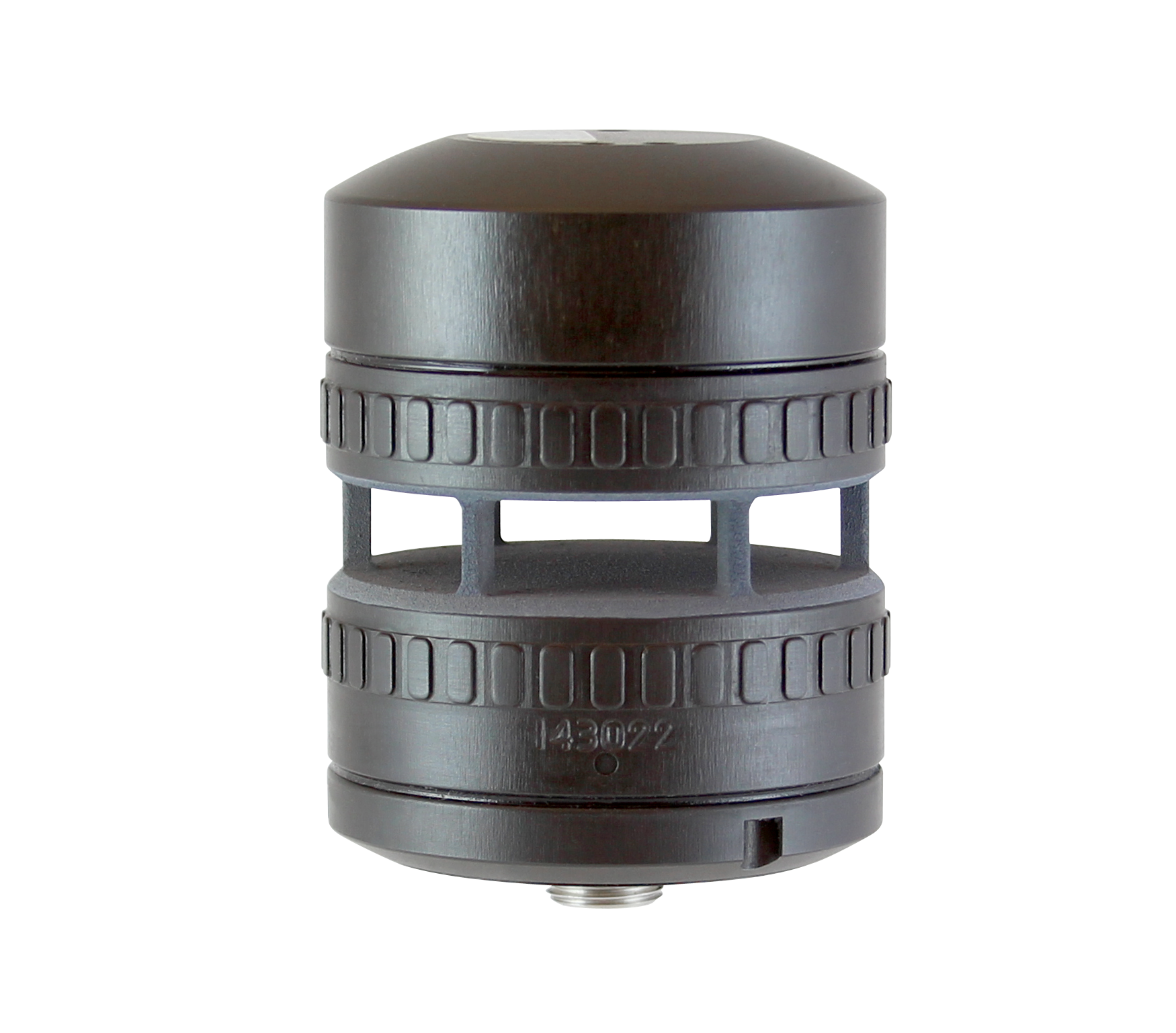
The FT742 Surface Mount (SM) wind sensor is designed for OEM integration into a wide range of engineering systems and has a compass and a heater. The sensor has been used in UAVs, drones, military vehicles, autonomous robots, handheld weather stations, CBRN detection units, drifter buoys, vehicle-mounted and ship-based meteorological systems.
The sensor can be rotated to ensure alignment with a standard reference, typically Magnetic North, or the integrated compass can calculate this automatically.
Small, low power, extremely rugged, and weighing only 252g, the FT742-SM is extensively tested and certified for vibration and shock resistance and RF immunity.
 Apply non-silicon lubricant to the o-ring and correctly position in the base of the sensor.
- Pass the cable through the mounting surface and attach it to the sensor.
- Sit the sensor on the mounting surface and make sure the o-ring is even all around.
- Rotate the sensor to align the mounting holes – note these are not equally spaced.
- Fit and tighten the mounting screws (not provided), ensuring they do not exceed a depth of 5mm into the base of the sensor.
For more information and guidance on installation in lightning and salt prone areas please consult the manual.
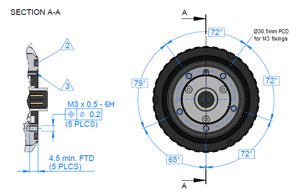
Marking 2 displays the location of the O-ring groove (FT O-ring part number FT029, manufacturer part number: 2-127 O-Ring EPDM 70 Shore). One O-ring is supplied with new sensors. The use of lubricant on the O-ring will depend on the material selection.
The O-ring compression fit is secured using 5x M3 fixings. The internal thread depth is 4.5mm, the length of fixings should be determined taking into account the thickness of the mounting surface. Regular condition monitoring of the sealing interface is recommended.
Caution: Excessive M3 fixing length may result in damage to the sensor thread and into the sensor.
The sensor requires a supply voltage of 6V to 30V DC (10V DC minimum if the heater is required). With the heater enabled, the power supply should be capable of supplying 2A (max), otherwise 25mA (29mA with the compass enabled).
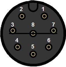
All electrical connections are made to the digital sensor via an 8-way multi-pole connector located in the base of the wind sensor housing. The connector pin designations are shown below. The connector conforms to IEC 61076-2-101.
Pin: 1
RS422: oV
RS485HD: oV
FT009 Wire Colour*: Brown
Pin: 2
RS422: +VE (6-30V)
RS485HD: +VE (6-30V)
FT009 Wire Colour*: White
Pin: 3
RS422: TX Data A –
RS485HD: N/C
FT009 Wire Colour*: Blue
Pin: 4
RS422: RX Data A –
RS485HD: Data A –
FT009 Wire Colour*: Black
Pin: 5
RS422: TX Data B +
RS485HD: N/C
FT009 Wire Colour*: Grey
Pin: 6
RS422: RX Data B +
RS485HD: Data B +
FT009 Wire Colour*: Pink
Pin: 7
RS422: N/C
RS485HD: N/C
FT009 Wire Colour*: Violet
Pin: 8
RS422: N/C
RS485HD: N/C
FT009 Wire Colour*: Orange
*Caution: Wire colours apply only to FT supplied FT009 cables. Other cables may use different colour schemes. Contact us for further information.
Heater and Set Point Temperature
To get the best from your sensor in icing conditions, the heater should be enabled and set to 30°C. This will help to prevent icing and water condensing in the measurement cavity, thus maximising data availability. In addition, a constant body temperature is better for the longevity of the electronic components.
The heater set point value can be adjusted using the HT command (refer to the user manual for more details) or alternatively using our Acu-Test Packs.
If the default current limit of 2A proves insufficient, it can be raised in software to 6A (in model V22 and above) but you must ensure that your power supply and cable can support at least 6 Amps.
Filtering
Always keep the sensor’s internal filter enabled. Where the wind sensor is used for control purposes, always use filtered data. The sensor is dispatched with the internal filter enabled by default and set to a filter length of 1.6 seconds.
Status Flag (Error Flag)
Digital: The sensor has an internal self-checking mechanism. It signals that a reading is invalid by setting an error flag character with in the wind velocity output message:
$WI,WVP=020.0,045,1*52〈cr〉〈lf〉
A value other than “0” here indicates an invalid reading of some sort was detected.
It is important that your data logging equipment or control system can process this invalid data appropriately. See the manual for more details on this.
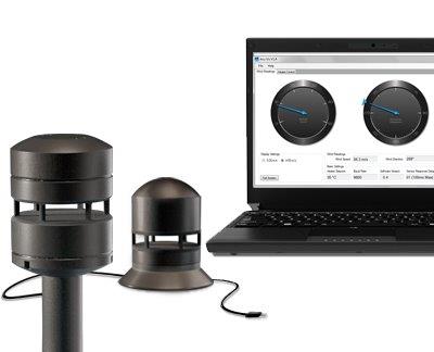 Testing of sensors is best performed with our Acu-Test Pack, which allows you to connect the sensor to a PC via a USB cable and view wind speed and direction readings in real-time. The pack also allows you to change some settings such as heater set point temperature.
In the case of digital sensors, a serial emulator program (such as Tera Term or HyperTerminal) will also function with the cable supplied in the Acu-Test Pack and is another way of testing communication. This allows the user to send commands and receive data from the sensor. Please note, however, that FT Technologies is not responsible for the content of external sites.
Further details are available in the product manual. Request a manual.
For details on cables and connectors please refer to Accessories.


