The FT742-DM50 (Direct Mount) fits directly onto a 47.9mm – 50.2mm (outer diameter) pipe and is ideal for a wide range of meteorological applications.
Powered by our Acu-Res® Technology the FT742-DM50 is unique in the market. It is a small, highly rugged, wind sensor that is maintenance-free and will last for years – even in the harshest conditions.
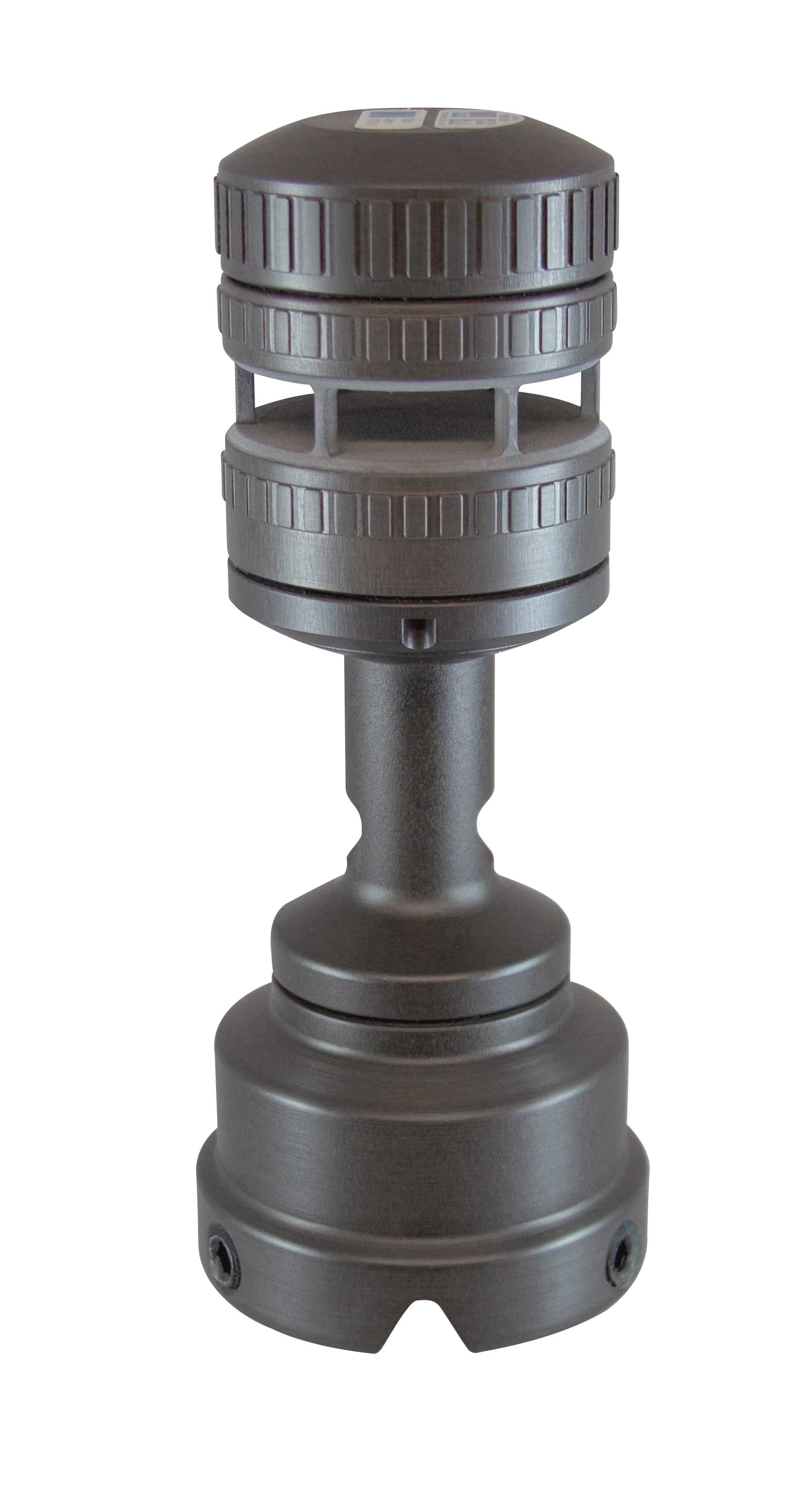

The FT742 DM50 (Direct Mount) is designed to fix directly to a pipe (47.9mm – 50.2mm nominal outer diameter). For lightning grounding :
- Check the Grounding-spring is fitted within the connector support.
- Fit the FT036 tapered pipe insert into the top of the pipe and fix into place with adhesive (not included).
- Pass the cable through the pipe and attach it to the sensor Slide the sensor firmly down over the pipe until it sits flat on the pipe.
- Rotate the sensor to align the North alignment feature (the North alignment is the V-shaped installation notch at the base of the sensor).
- Tighten the 3x FT037 self-locking fasteners carefully to ensure an even distribution of pressure.
For more information and guidance on installation in lightning and salt prone areas please consult the manual.
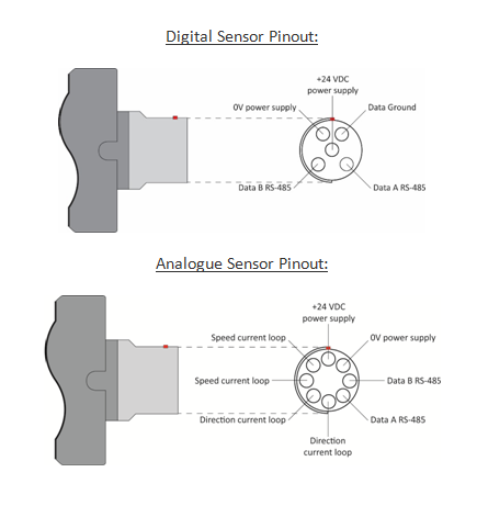
The FT7 Series sensor requires a supply voltage of 12V-30V DC (24V DC). The power supply should be capable of supplying 6A (max) if the heater is enabled, (30mA if the heater is disabled). All electrical connections are made to the sensor via a multipole connector manufactured by Fischer or ODU (in the case of digital sensors, using cable side connectors of the following part numbers: SE104Z053-130/8.7 or SX2F1C-P05NJH9-0001 respectively. In the case of analogue sensors, using cable side connectors: SS104Z129-1 or SX2F1C-P08NJH9-0001 respectively).
The pinout from the base of the Direct Mount sensor is as follows:
Heater and Set Point Temperature
To get the best from your sensor in icing conditions, the heater should be enabled and set to 30°C. This will help to prevent icing and water condensing in the measurement cavity, thus maximising data availability. In addition, a constant body temperature is better for the longevity of the electronic components.
The heater set point value can be adjusted using the HT command (refer to the user manual for more details) or alternatively using our Acu-Test Packs.
If the default current limit of 4A proves insufficient then it can be raised in software to 6A but you must ensure that your power supply and cable can support at least 6 Amps.
Filtering
Always keep the sensor’s internal filter enabled. Where the wind sensor is used for control purposes, always use filtered data. The sensor is dispatched with the internal filter enabled by default and set to a filter length of 1.6 seconds.
Status Flag (Error Flag)
Analogue: The sensor indicates errors and out-of-range measurements by setting the current loops to levels outside of the normal 4-20mA range. It is important that your data logging equipment or control system can process this invalid data appropriately. See the manual for more details.
Digital: The sensor has an internal self-checking mechanism. It signals that a reading is invalid by setting an error flag character with in the wind velocity output message:
$WI,WVP=020.0,045,1*52〈cr〉〈lf〉
A value other than “0” here indicates an invalid reading of some sort was detected.
It is important that your data logging equipment or control system can process this invalid data appropriately. See the manual for more details on this.
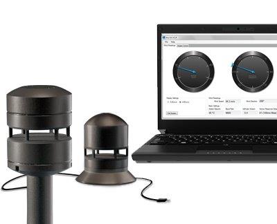 Testing of sensors is best performed with our Acu-Test Pack, which allows you to connect the sensor to a PC via a USB cable and view wind speed and direction readings in real-time. The pack also allows you to change some settings such as heater set point temperature.
In the case of digital sensors, a serial emulator program (such as Tera Term or HyperTerminal) will also function with the cable supplied in the Acu-Test Pack and is another way of testing communication. This allows the user to send commands and receive data from the sensor. Please note, however, that FT Technologies is not responsible for the content of external sites.
Further details are available in the product manual. Request a manual.
For details on cables and connectors please refer to Accessories.
Download the Acu-Test datasheet for the digital wind sensor
Download the Acu-Test datasheet for the analogue wind sensor


